Difference between revisions of "APS Arriflex 16SR2 Operating Guide"
(→MODIFIED BODY) |
|||
| Line 156: | Line 156: | ||
# Attach any extra body modifiers (follow focus, grip handle) | # Attach any extra body modifiers (follow focus, grip handle) | ||
# Push the motor switch to “ON” to engage shooting. | # Push the motor switch to “ON” to engage shooting. | ||
| + | |||
| + | ===NEUTRAL DENSITY FILTERS=== | ||
| + | Use the following chart to adjust your f-stop according to the ND filter you're using. | ||
| + | |||
| + | [[file:ND.png]] | ||
[[Category:Media Loan]] | [[Category:Media Loan]] | ||
Revision as of 13:53, 4 August 2016
The Arriflex 16SRII at APS is for restricted use only. Proficiencies for this camera are only provided through approved programs and cannot are not available for other students.
Contents
INTRO
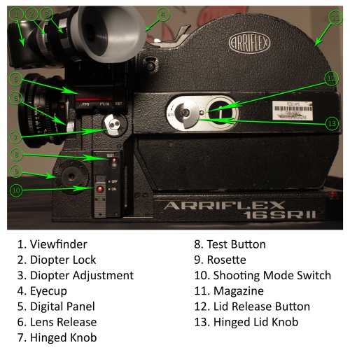
The Arriflex 16SRII is is a 16mm motion picture camera created by Arri. The “SR” stands for Silent Reflex. This camera is distinguished by its small portable profile, multidirectional viewfinder, crystal controlled motor and quick-change magazine.
The Arriflex available at APS has a modified body and will appear different than cameras of the same model in instruction manuals. A full manual can be found here.
IN THE KIT
Arriflex 16SRII modified camera body
2 covers: Camera body and magazine
Hand grip
Follow focus, Support & Plate
2 Batteries, adapter & charger
8mm lens
10mm-100mm lens
Mutar f=6mm
Mutar 2x
Shoulder pad
CARE
DO NOT:
Drop this camera
Point the camera toward the sun
Submerge this camera in water
Leave this camera in excessive heat or cold (such as a car)
Expose it to extreme weather conditions
Use a blow dryer to blow dust from the camera
Store next to/with corrosive materials
Use excessive physical force
STORAGE
When storing this kit, remove the lenses and insert the lens body cap back onto the camera. Remove the magazines, as well as the battery and adapter and store them separately as well. Detach all lens modifiers from the lenses.
Put the BODY COVER on the camera body. Put the MAGAZINE COVER on the magazine (attaches over the throat).
CAMERA BODY PARTS
Viewfinder
The viewfinder on this camera can be turned and swiveled and has fully automatic image compensation. It can be moved on three planes and it can be used for viewing with the left or right eye. The image will be displayed correctly no matter which position the viewfinder is in.
Diopter
The diopter on the Arriflex 16SR2 is adjustable to your viewing preferences. The purpose of the diopter is to focus the viewfinder to your eye. THE DIOPTER MUST BE FOCUSED TO THE INDIVIDUAL USER BEFORE THE LENS IS FOCUSED. If you do not focus the diopter first, your images could be out of focus.
To focus the diopter, unlock it by turning the LOCK RING and then turn the DIOPTER ADJUSTMENT until the guides in the viewfinder are in focus.
The dowser, a mechanism inside the viewfinder, needs to be closed when your eye is not on the eyecup to prevent your film from fogging. The dowser on the Arriflex 16SR2 can be set to automatically open/close when your eye is set onto the eyecup. To adjust the functionality of the dowser, you can remove the EYECUP and turn the ring. The eyecup is magnetized and can be easily be put back into place.
Mirror Shutter Stop
Each time the camera is switched off the motor stops the mirror shutter in such a position that the finder remains open for viewing. The opening of the shutter is 180 degrees. The mirror shutter can also be rotated by hand with the hinged knob.
MODIFIED BODY
Footage Counter
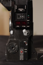
There are multiple footage counters on the magazine of this camera. Do not use these. There is an accurate digital FOOTAGE COUNTER located on the side of the camera body on the DIGITAL PANEL. A battery must be attached to view/access it. Press the RST “reset” button after mounting a magazine with new film and before shooting to count your footage. Measurements are displayed in feet.
FPS
FPS (frames per second) is also displayed digitally on the side of the camera, next to the footage counter. You can adjust the FPS with the SPEED CONTROL located above the DIGITAL PANEL. Note: the faster the FPS, the quicker the battery is drained. If the battery is too low to keep up with the set FPS, it will compensate by dropping the FPS accordingly. Make sure to read the FPS number on the digital panel to know exactly what the camera is shooting at.
ACCESSORIES
Follow Focus / Support
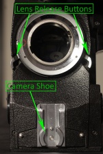
The lightweight support is used to mount the follow focus and is designed for filming from the shoulder. The support is placed in the CAMERA SHOE (under the lens mount on the front of the camera) and is fastened with the KNURLED SCREW, which is found between the two support rods. The FOLLOW FOCUS can now be pushed on the rods, positioned as desired, and held secure by the TIGHTENING SCREW.
Hand Grip
The HAND GRIP provides stabilization to the camera and is equipped with a cable release for easy access to shooting. It is screwed into the ROSETTE on either side of the camera and is plugged into the 4-POLE PLUG on the right side.
Mutar
6mm
The Carl Zeiss Mutar f=6mm is a wide angle supplementary lens that fits onto the front of the zoom lens (the 10-100mm in the kit). This mutar converts the zoom into a 6mm super wide angle prime – you will not be able to change focal length when using it. To utilize the Mutar 6mm, mount it onto the zoom and set the zoom to MACRO MODE. You can do this by pressing the macro button on the lens (silver knob with a green dot) and turning the focal length ring all the way to the left.
2x
The Mutar 2x doubles the focal length of a lens. Instead of fitting onto the front of the lens like the Mutar 6mm, the Mutar 2x fits into the lens mount onto the camera body. A lens, either the 8mm or 10-100mm, then gets inserted into the Mutar 2x. It converts the 8mm into a 16mm, and the 10-100mm to a 20-200mm.
LENS MOUNTING
Steps:
- Press the LENS RELEASE BUTTONS on both sides of the lens mount simultaneously to release the body cap.
- Line up the mount notches on the lens with the slots on the catch ring on the body of the camera and set it into place.
- Turn the lens until it locks into place
To dismount: Press the release buttons together, turn the lens counter clockwise, and pull the lens out.
MAGAZINE LOADING
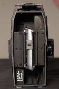
There are two magazines with this kit. One is set-up to be used with daylight spools, and the other is for 400’ rolls of film. The daylight spools can be loaded in dim lighting, but the 400’ rolls need to be loaded in a dark room or changing bag.
Daylight spools vs. Film rolls
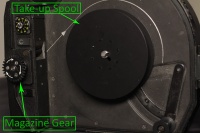
Take-up: The 400’ roll requires the EXPANDABLE CORE on the take-up side. The daylight spool can be used with the expandable core, but it is recommended that you use an empty take-up spool instead. The magazine for daylight is already set-up for this.
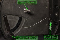
Pressure Roller: These are located inside the magazine on both the supply and take up sides. Only use these with a film roll. Do not use with a daylight spool.
Supply: On the supply side of the magazine, the film rolls are mounted onto the CORE ADAPTER. The daylight spools are set directly onto the SPOOL MOUNT and latched down.
As most of the filmmaking needs at TESC are met with daylight spools, the rest of this instructional portion is written with that assumption. The film must be threaded with the emulsion inwards.
Loading steps
- Open the MAGAZINE LID on the film supply side by pressing the LID RELEASE BUTTON, turning the HINGED LID KNOB, and swinging the lid open.
- Flip up the latches on the SPOOL MOUNT. Load the spool onto the mount with the film pointing in the direction of the arrows (counter-clockwise with the perforation up). Push the latches back down, locking the spool into place. DO NOT ENGAGE THE PRESSURE ROLLER.
- Slide the film into the FEED SLOT on the magazine (little window on the inside). You can turn the MAGAZINE GEAR slightly in the direction of the arrow printed on it until a perforation hole is gripped. DO NOT FORCE THE GEAR – this could rip sprockets. Advance the gear until the film is pushed through to the magazine THROAT.
- Shut the lid on the supply side and turn the hinged knob to lock. The rest of the loading can be done in full light.
- Pull the film out from the throat and measure it to the mark on the bottom of the magazine (white line). This creates the correct loop size. DO NOT LET THE FILM ADVANCE ANY FURTHER – this will cause too much slack.
- Open up the MAGAZINE LID on the take-up side. Push the film, without changing its length, into the slot in the throat on the take-up side (bottom-right of the throat) until the gear moves in the direction of the arrow. Again, DO NOT FORCE THE GEAR. After it is correctly set in place, you can then use the gear to advance the film into the take-up area.
- Advance the gear and load the film head into the slot on the spool in the direction of the arrow printed on the magazine. After it is secured on the spool, make the film is taut by holding the gear in place with one hand and turning the spool clockwise with the other. This will take up the slack without feeding through more film. DO NOT ENGAGE THE PRESSURE ROLLER on this side either.
- Make sure the take-up spool is secured in place, then shut and lock the lid on the take-up side.
- Set the film in the throat into the HOOKS of the PRESSURE PLATE.
- After you have loaded the film in the magazine, mounted the magazine to the camera body, and attached a battery, hold the TEST button until you hear a slight click. This ensures the film has been correctly set.
Unload
Open the take-up side of the magazine, press the SPOOL RELEASE, and take off the spool. It’s best to unload in subdued light.
Extra reminders
- Do not engage the pressure rollers on the supply or take-up sides of the magazine
- Do not force the magazine gear as this could cause sprockets to rip. If your sprockets rip, cut off the damaged sections of film before proceeding.
- If you do not intend to use the magazine immediately, attach the camera body cover and magazine cover.
- TEST the film when you’re done loaded and the magazine is mounted onto the body.
MAGAZINE MOUNTING
To mount the magazine
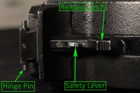
- Engage the HINGE PIN on the magazine into the SNAP CATCH on the camera body and push the magazine downwards; a click is heard when the magazine sets into position.
- Lock the RELEASE CATCH by pushing the SAFETY LEVER to the “LOCK” position.
To dismount the magazine
- Pull the SAFETY LEVER from “LOCK” to the “OFFEN/OPEN” position.
- Depress the RELEASE CATCH and raise the magazine to remove it from the camera’s SNAP CATCH.
BATTERY
A special hinged battery adapter is needed to use the included batteries.
Battery Mounting Steps
- Mount the magazine.
- Plug the BATTERY ADAPTER into the POWER CONNECTION SOCKET on the back of the camera body and tighten the attached screw.
- Fit the adapter into the slot on the bottom of the battery. Push the battery onto the adapter.
- When fitted correctly, tilt the battery back onto the back of the magazine. These pieces are magnetized and should snap into place.
BASIC STEPS FOR OPERATION
- Load the film into the magazine
- Mount the magazine onto the camera body
- Mount a lens to the body
- Attach a battery
- Set the diopter
- Attach any extra body modifiers (follow focus, grip handle)
- Push the motor switch to “ON” to engage shooting.
NEUTRAL DENSITY FILTERS
Use the following chart to adjust your f-stop according to the ND filter you're using.


