Difference between revisions of "APS Sound Devices 302 Portable Field Mixer"
| Line 85: | Line 85: | ||
===SLATE MIC & TONE OSCILLATOR=== | ===SLATE MIC & TONE OSCILLATOR=== | ||
A cute feature of this mixer is its built in slate mic and tone feature. This is one more reason this mixer is great for film audio. Use the '''slate mic''' by holding the "MIC/1K" switch to the right. Use it to briefly notate which scene is being shot. Use the '''tone oscillator''' to set the levels on devices that are post-mixer in the signal path. The tone oscillator emits a 1 kHz tone at 0dBu. You can use this to set devices level to unity (0 dB) and ensure proper recording. This audio from the slate mic and tone oscillator are recorded on all channels. | A cute feature of this mixer is its built in slate mic and tone feature. This is one more reason this mixer is great for film audio. Use the '''slate mic''' by holding the "MIC/1K" switch to the right. Use it to briefly notate which scene is being shot. Use the '''tone oscillator''' to set the levels on devices that are post-mixer in the signal path. The tone oscillator emits a 1 kHz tone at 0dBu. You can use this to set devices level to unity (0 dB) and ensure proper recording. This audio from the slate mic and tone oscillator are recorded on all channels. | ||
| − | [[ | + | [[category:APS Gear Guides]] |
Latest revision as of 11:52, 22 January 2021
Contents
INTRO
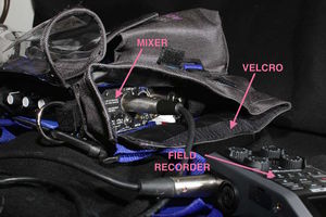
Designed to capture audio for film, this high-end mixer features three XLR inputs and two XLR outputs. Our kit includes a power adapter but can also be powered by three AA batteries for use in the field. Each channel has both input gain and volume knobs, 12V or 48V phantom power, a variable low-cut filter, and a pan selector switch. This mixer's other capabilities like stereo outputs (hence the 3 inputs with only 2 outputs) makes is a versatile tool. Its daylight-visible LED meter, carrying bag that can consolidate the mixer, recorder, and cables makes it convenient for quickly capturing professional audio.
GETTING SET UP
Depending on your power source move the power switch in the bottom right corner to the correct position (INT for using battery bower, EXT for power adapter). Some lights should light up to indicate the mixer is on.
INS AND OUTS
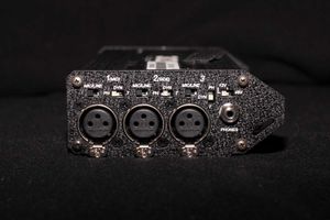
Plug your inputs into the left side of the mixer, outputs go in the right side. Next to each input is a mic/line switch and and mic powering switch. Select "PH" to activate phantom power on that input. Either 12V or 48V phantom power can be selected with the switch in the upper right corner. This applies to all inputs with "PH" selected. Most condenser mics that need phantom power will use 48V, but always double check and know your microphones! "DYN" stands for "dynamic". Dynamic microphones don't need phantom power. The "T" setting stands for T-power which is wired differently for a few older microphones. T-power is almost never needed. DO NOT USE T POWER WITH RIBBON MICROPHONES BECAUSE IT CAN DESTROY THEM!
Despite being an output, the headphone jack is located on the left side of the mixer with the rest of the inputs.
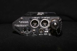
Plug your outputs into the right side of the mixer. There are two XLR outputs. This is for stereo recording and will be explained below. For now, plug in your outputs and connect them to their destination, usually a recording device.
You will have to tell the mixer where to send each input. This allows for greater control of your signal flow and is done using the "L C R" pan switch assigned to each channel on the front panel of the mixer. Switched to "L" sends that channel to the left output and "R" to the right. "C" sends the channel equally to both outputs.
Here are some scenarios to help understand when to use each pan setting:
- You have two microphone and want the greatest control over your levels both while recording and in post-production. If one mic is close to your subject and the other is capturing more ambient room noise or is positioned in a place that is exposed to wind, this would be and ideal situation to pan your two inputs to separate outputs (L + R).
- You are filming two people talking and are using a lavalier mic on each person (inputs 1 & 2). You are also using a boom mic to capture the fuller sound of the room (input 3). Sending both lav mics to the same track will make editing in post-production much easier since they will already be consolidated and just need to be synced with the video. These could both be assigned to the left output (L). The boom however will sound different than the lavs and you might want to adjust the levels independently in post or use different effects to process its audio. Sending the boom to the right output (R) will allow you to keep the sources separate while still being able to capture audio from a variety of sources and save you time in post.
- If you needed to have three input sources, capturing similar sources, you could use the pan switches to send all of your inputs bunched together to one output while isolating one of those inputs to its own output channel in order to have more freedom in post. For example, if you wanted input 2 to be an isolated recording, you would pan input 1 right, input 2 center (so it's sending to both outputs), and input 3 right. Now the right output will include all three microphones on one track and the left will keep input 2 isolated.
SETTING LEVELS
Now that your inputs and outputs are setup, it's time to set the levels. This is done from the front panel of the mixer. Each channel has a coarse and a fine trim knob. The course knob should be set first. This is the smaller black knob to the upper right of the fine trim, larger knob. The coarse trim knob is spring loaded. Pushing it in will make it pop out so it can be adjusted. Push it back in so it will be out of the way and safe from accidental movements while recording. Your subject needs to be making noise before you set your levels. If you're recording a person, have them talk while you do this. Ask them about their breakfast, or something like that. To set this knob, first set the fine trim knob to 0dB (when a level is at 0, it is at "unity"). Then adjust the coarse trim so the LED meter is registering somewhere in the mid range. Now use the fine trim knob to bring the level up so it sits around -6dB on the meter. The fine trim knob is useful for making quick and small adjustments while recording. This is especially useful if the subject does not have a consistent volume.
LOW-CUT & LIMITER
Each channel has the option to apply a low-cut filter (also known as a high-pass filter). The switch is variable and can used for rolling off at 80Hz or 160Hz. This filter attenuates sound at a rate of 12dB per octave. Use this option to reduce low and unwanted rumbles that can come from wind, room noise, and other background muddiness. A low-cut filter is almost always a good choice for recording voices.
There is a single limiter switch located just right of the third gain knob. It has three positions, OFF, LIM, and LINK. LIM is for dual-mono use and applies a limiter to inputs and outputs. LINK is for stereo operation. By default, the limited is set to a threshold of +20dB.
MONITORING//METERING
While a decent pair of headphones should always be used to monitor when recording audio (also available as APS and Media Loan,) a visual meter is the primary way to confirm that levels are set and being adjusted properly. This mixer has an LED array that displays the level of each channel.
LED METER
By default, the meter will display output bus levels. It is also capable of sourcing PFL (pre-fader listen) levels, and return input levels. The output bus levels will be the main source to be concerned with. The other two will not usually be necessary to view. From sourcing the outputs levels, the meter can display a variety of information. This is selected by pressing the PK/VU button. PK stands for "peak" and VU for "volume units". By pressing that button, the selections cycled are VU, Peak, Peak-Hold and VU combination, and Peak and VU combination. If these terms are arbitrary to you, stick with VU. This selection will not affect your audio in anyway, just how it is visually represented to the operator.
The meter is designed to be used in all lighting situations, even outdoors. Adjust the brightness of the meter by pushing the button with a sun next to it at the bottom left of the meter.
HEADPHONE MONITORING
Headphone monitoring adjustments are made with the two knobs directly under the meter. The right knob changes the volume in the headphones. Set this to a comfortable level but remember that this headphone volume does not accurately reflect the output volume being recorded. The left knob determines what audio is being sent to the headphones. This mixer offers 11 various sources. Most of these will be arbitrary for most users and selecting "M" or "ST" will do you no wrong. See the chart below for a detailed explanation of each selection.
The LED to the right of the right headphone knob labeled "HP" indicates the headphone circuit is overloading. Turn down your knob!
| HP Source | Description |
|---|---|
| 1 (PFL) | PFL solo monitoring of the Channel 1 input signal. The channel is monitored in dual-mono. Pre-Fader, postLimiter,
and post-High-Pass. Useful for setting the channel gain. |
| 2 (PFL) | Same as above, for Ch. 2. |
| 3 (PFL) | Same as above, for Ch. 3. |
| L | Left output bus, monitored in dual-mono. |
| R | Right output bus, monitored in dual-mono. |
| M | Summed mono of the left and right output bus. |
| ST | Stereo monitoring of the master output bus. This is the primary monitoring path. |
| RTN | Stereo return from the RTN monitor input path. |
| M-MS | Monitoring of the mono signal of an MS stereo signal. |
| ST-MS | Monitoring of discrete MS signals in the headphones as a decoded stereo signal. |
| RTN-MS | Monitoring of discrete MS return signal in the headphones as decoded stereo signal. |
STEREO RECORDING
The 302 can record in stereo with either an X/Y pattern or an MS (mid-side) pattern. These are two different miking techniques and require different microphones and different placements. If recording stereo, the technique (X/Y or MS) must be chosen in the set-up menu of the mixer. If planning to record in stereo, please ask us how to do this and we can offer some consulting.
302 STEREO OPERATION NOTES
In an X/Y link, channels 1 and 2 pan switches continue to reflect the same signal routing for each channel. Channel 2's fader controls the overall level of the stereo pair. The trim knobs and low-cut filters remain independent. In an MS link input 1 should be connected to the mid mic and input 2 to the side mic, as labeled on the side of the mixer. Channel 2's fine gain (fader) knob now controls the overall gain of the linked pair. Channel 1's fine gain knob (fader) as well as each channels pan switches are disabled. The coarse gain knob for each channel controls the mid and side levels respectively. There is also a polarity reverse switch just next to Channel 1's coarse gain knob. This flips the polarity of input 2 relative to inputs 1 and 3. This may be needed for MS stereo linking.
SLATE MIC & TONE OSCILLATOR
A cute feature of this mixer is its built in slate mic and tone feature. This is one more reason this mixer is great for film audio. Use the slate mic by holding the "MIC/1K" switch to the right. Use it to briefly notate which scene is being shot. Use the tone oscillator to set the levels on devices that are post-mixer in the signal path. The tone oscillator emits a 1 kHz tone at 0dBu. You can use this to set devices level to unity (0 dB) and ensure proper recording. This audio from the slate mic and tone oscillator are recorded on all channels.


