Difference between revisions of "BeatStepPro MIDI to CV"
(Added text description.) (Tag: VisualEditor) |
(Added images with descriptions.) (Tag: VisualEditor) |
||
| Line 9: | Line 9: | ||
== Step 1: Choose the Correct Port == | == Step 1: Choose the Correct Port == | ||
| + | [[File:Ableton midi tracks.png|alt=A screenshot of three side-by-side MIDI track header strips from Ableton Live, showing the routing configuration needed to send MIDI from the DAW to the BeatStep Pro. Each track displays an identical set of controls: Track name/number row: Shows track identifiers "949", "1143", and "94" with colored activity indicators MIDI From: All three tracks set to "All Ins" and "All Channels" Monitor: "Auto" is selected (highlighted) on all three tracks, with "In" and "Off" as the unselected options MIDI To: All three tracks route to "Arturia BeatStepPro" Channel: The only differing setting — Track 1 is set to "Ch. 1", Track 2 to "Ch. 2", and Track 3 to "Ch. 10" This screenshot illustrates the channel-assignment pattern that drives Sequence 1, Sequence 2, and the drum gates on the BeatStep Pro respectively.|thumb]] | ||
| + | |||
When setting MIDI output in Ableton, select the port labeled '''Arturia BeatStepPro''' — ''not'' the editor port. The editor port is reserved for Arturia's MIDI Control Center software and will not pass notes to the CV outputs. | When setting MIDI output in Ableton, select the port labeled '''Arturia BeatStepPro''' — ''not'' the editor port. The editor port is reserved for Arturia's MIDI Control Center software and will not pass notes to the CV outputs. | ||
| Line 30: | Line 32: | ||
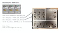
== Step 4: Patch the CV Outputs == | == Step 4: Patch the CV Outputs == | ||
| + | [[File:Beatstep cv interface.jpg|alt=A color photograph of a custom brushed-metal enclosure sitting on a wooden surface, serving as the CV patch bay for the BeatStep Pro. The box is divided into three labeled sections by engraved or stamped lettering: Upper-left section — Sequencer outputs: Two rows of three 1/4" jacks. The top row is labeled "SEQUENCE 1" with individual jack labels "VELO", "GATE", and "PITCH" beneath them. The bottom row, labeled "SEQUENCE 2", mirrors the same three-jack layout for velocity, gate, and pitch output. Upper-right section — MIDI and clock: Two jacks stacked vertically. The top jack is labeled "IN" (MIDI input) and the bottom jack is labeled "OUT" under the heading "CLOCK", providing clock output to sync external gear. Lower section — Drum gates: A horizontal row of eight 1/4" jacks labeled "DRUM GATES", with each jack individually numbered 1 through 8 in a staggered two-row pattern. These provide individual gate triggers for the BeatStep Pro's eight drum tracks. The enclosure has a raw, DIY-fabricated aesthetic with hand-stamped lettering.|thumb]] | ||
| + | |||
The custom interface box exposes the BeatStep Pro's CV signals on 1/4" jacks: | The custom interface box exposes the BeatStep Pro's CV signals on 1/4" jacks: | ||
* '''Sequence 1 and 2:''' each have three jacks — VELO (velocity), GATE, and PITCH | * '''Sequence 1 and 2:''' each have three jacks — VELO (velocity), GATE, and PITCH | ||
Revision as of 13:47, 16 April 2026
Contents
Connecting the BeatStep Pro to Ableton Live for MIDI-to-CV
Overview
The Arturia BeatStep Pro can act as a MIDI-to-CV converter, letting Ableton Live control analog gear (like Eurorack modules or vintage synths) through control voltage signals. This setup routes MIDI from Ableton into the BeatStep Pro, which then outputs pitch, gate, velocity, and drum triggers as CV through a custom patch box.
Step 1: Choose the Correct Port

When setting MIDI output in Ableton, select the port labeled Arturia BeatStepPro — not the editor port. The editor port is reserved for Arturia's MIDI Control Center software and will not pass notes to the CV outputs.
Step 2: Set Up MIDI Tracks in Ableton
You can set up up to three MIDI tracks depending on what you need to control — only create tracks for the voices you actually want to use. Each track is configured the same way except for the output channel:
- MIDI From: All Ins, All Channels
- Monitor: Auto
- MIDI To: Arturia BeatStepPro
Assign each track you create to the appropriate MIDI channel:
- Channel 1 — drives Sequence 1 Output (pitch, gate, and velocity CV outputs)
- Channel 2 — drives Sequence 2 Output (pitch, gate, and velocity CV outputs)
- Channel 10 — drives the eight drum gate outputs.
For example, if you only need melodic control over one synth, a single track on Channel 1 is enough. If you want drums plus one melodic voice, use two tracks (Channels 1 and 10), and so on.
Step 3: Understand the Channel Mapping
The BeatStep Pro listens on specific MIDI channels for specific functions:
- Channel 1 controls the first melodic sequencer voice. Notes you play or sequence on this track come out of the Sequence 1 pitch, gate, and velocity jacks.
- Channel 2 does the same for the second melodic voice on the Sequence 2 jacks.
- Channel 10 controls the drum section. MIDI notes 36 through 43 each trigger one of the eight drum gate outputs (note 36 → drum 1, note 37 → drum 2, and so on).
Step 4: Patch the CV Outputs

The custom interface box exposes the BeatStep Pro's CV signals on 1/4" jacks:
- Sequence 1 and 2: each have three jacks — VELO (velocity), GATE, and PITCH
- Drum Gates: eight numbered jacks (1–8) for individual drum triggers
- Clock Out: sends timing pulses to sync other gear
- IN: MIDI input
Patch these to the corresponding inputs on your analog synth or modular system.
Step 5: Know the Voltage Standards
The CV signals follow common modular conventions:
- Pitch: 1 volt per octave (1v/oct) — the standard for most Eurorack and vintage synths
- Gate: 0v when a note is off, 12v when a note is on — a relatively hot gate signal, compatible with most modular gear
Putting It All Together
Once your Ableton tracks are routed to the appropriate channels on the BeatStepPro port, you can sequence melodic parts in Ableton and hear them come out of your analog gear as pitched CV, while drum patterns on Channel 10 fire gates to trigger percussion modules. Ableton becomes the brain; the BeatStep Pro becomes the translator.