Difference between revisions of "Mackie Documentation"
(Added text description of Mackie Channel) (Tag: VisualEditor) |
|||
| Line 9: | Line 9: | ||
</gallery> | </gallery> | ||
| − | = | + | = Mackie Channel Signal Flow = |
<gallery> | <gallery> | ||
Mackie_Channel_Flow_w_Direct.pdf | Mackie_Channel_Flow_w_Direct.pdf | ||
</gallery> | </gallery> | ||
| + | |||
| + | == Overview == | ||
| + | This document is a block diagram showing the signal path through a single channel on a Mackie analog mixer — tracing how audio travels from the input jack through the channel's processing stages and out to the various destinations (main stereo outs, sub groups, direct out, and aux sends). | ||
| + | |||
| + | == The Main Signal Path == | ||
| + | Audio flows left-to-right through the channel strip in this order: | ||
| + | # '''INPUT''' — the physical jack where your source (mic, instrument, line-level device) enters the channel | ||
| + | # '''TRIM''' — input gain stage that sets the proper signal level for the channel | ||
| + | # '''INSERT''' — send/return point for patching in external processing (compressors, effects, etc.) | ||
| + | # '''LOW CUT''' — high-pass filter to remove low-frequency rumble | ||
| + | # '''EQ''' — tone-shaping equalizer | ||
| + | # '''MUTE''' — a switch that silences the channel when engaged | ||
| + | # '''FADER''' — the channel volume control | ||
| + | # '''PAN''' — places the signal in the stereo field (left-to-right) | ||
| + | # '''ASSIGN''' — routes the post-fader signal to the chosen stereo output bus | ||
| + | |||
| + | == Output Destinations == | ||
| + | After the assign stage, the signal can be sent to any of the '''Stereo Outs''': | ||
| + | * '''L/R''' — the main mix output | ||
| + | * '''1/2''' — subgroup bus 1/2 | ||
| + | * '''3/4''' — subgroup bus 3/4 | ||
| + | A channel can be assigned to any combination of these buses simultaneously. | ||
| + | |||
| + | == The Direct Out == | ||
| + | A '''Direct Out''' tap is taken immediately after the fader (post-fader, post-mute), providing a '''mono''' feed of that single channel. This is useful for multitrack recording — each channel can be sent to its own recorder input independently of the main mix. | ||
| + | |||
| + | == Aux Sends and the Pre/Post Switch == | ||
| + | The channel feeds two auxiliary sends, '''AUX 1''' and '''AUX 2''', which are commonly used for monitor mixes or effects sends. A '''PRE SWITCH''' determines where the aux send taps the signal from: | ||
| + | * '''"PRE" signal''' — taken ''before'' the fader and mute (after EQ). The aux send level is independent of the channel fader — useful for stage monitor mixes, where the performer's monitor level should stay constant even when the front-of-house fader moves. | ||
| + | * '''"POST" signal''' — taken ''after'' the fader and mute. The aux send level follows the fader — useful for effects sends (reverb, delay), so the effect level tracks the channel's mix level. | ||
| + | Each aux send has its own level knob (shown as AUX 1 and AUX 2 with their rotary controls) before going to the aux output buses. | ||
| + | |||
| + | == Summary == | ||
| + | A signal entering the channel is gained, filtered, EQ'd, muted (or not), and faded — then it splits three ways: to the '''assign matrix''' for the main stereo/subgroup mix, to the '''direct out''' for isolated recording, and to the '''aux sends''' (pre- or post-fader) for monitors and effects. | ||
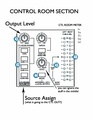
== Control Room Out == | == Control Room Out == | ||
Revision as of 14:07, 16 April 2026
Contents
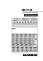
Full Manual
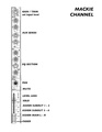
Channel Print-Out
Mackie Channel Signal Flow

Overview
This document is a block diagram showing the signal path through a single channel on a Mackie analog mixer — tracing how audio travels from the input jack through the channel's processing stages and out to the various destinations (main stereo outs, sub groups, direct out, and aux sends).
The Main Signal Path
Audio flows left-to-right through the channel strip in this order:
- INPUT — the physical jack where your source (mic, instrument, line-level device) enters the channel
- TRIM — input gain stage that sets the proper signal level for the channel
- INSERT — send/return point for patching in external processing (compressors, effects, etc.)
- LOW CUT — high-pass filter to remove low-frequency rumble
- EQ — tone-shaping equalizer
- MUTE — a switch that silences the channel when engaged
- FADER — the channel volume control
- PAN — places the signal in the stereo field (left-to-right)
- ASSIGN — routes the post-fader signal to the chosen stereo output bus
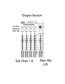
Output Destinations
After the assign stage, the signal can be sent to any of the Stereo Outs:
- L/R — the main mix output
- 1/2 — subgroup bus 1/2
- 3/4 — subgroup bus 3/4
A channel can be assigned to any combination of these buses simultaneously.
The Direct Out
A Direct Out tap is taken immediately after the fader (post-fader, post-mute), providing a mono feed of that single channel. This is useful for multitrack recording — each channel can be sent to its own recorder input independently of the main mix.
Aux Sends and the Pre/Post Switch
The channel feeds two auxiliary sends, AUX 1 and AUX 2, which are commonly used for monitor mixes or effects sends. A PRE SWITCH determines where the aux send taps the signal from:
- "PRE" signal — taken before the fader and mute (after EQ). The aux send level is independent of the channel fader — useful for stage monitor mixes, where the performer's monitor level should stay constant even when the front-of-house fader moves.
- "POST" signal — taken after the fader and mute. The aux send level follows the fader — useful for effects sends (reverb, delay), so the effect level tracks the channel's mix level.
Each aux send has its own level knob (shown as AUX 1 and AUX 2 with their rotary controls) before going to the aux output buses.
Summary
A signal entering the channel is gained, filtered, EQ'd, muted (or not), and faded — then it splits three ways: to the assign matrix for the main stereo/subgroup mix, to the direct out for isolated recording, and to the aux sends (pre- or post-fader) for monitors and effects.